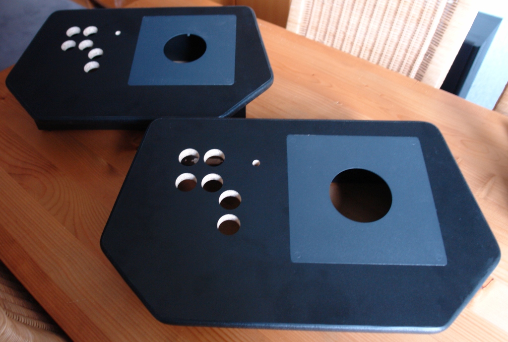
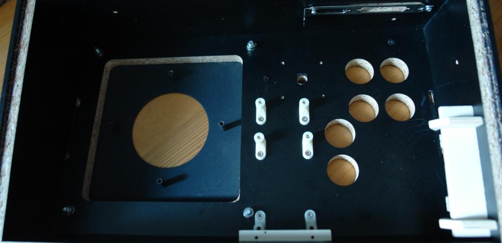
In whatever fields I might be talented, there is one in which I definitely have no knack: Woodworking. Moreover, I don't posess a workbench or tools for carpentry. Therefore, it was an easy and fast decision to commission the fabrication of the control panel housings to a carpenter in my neighbourhood. Provided with a construction plan and a set of specifications he manufactured the panels very nicely on a CNC mill:
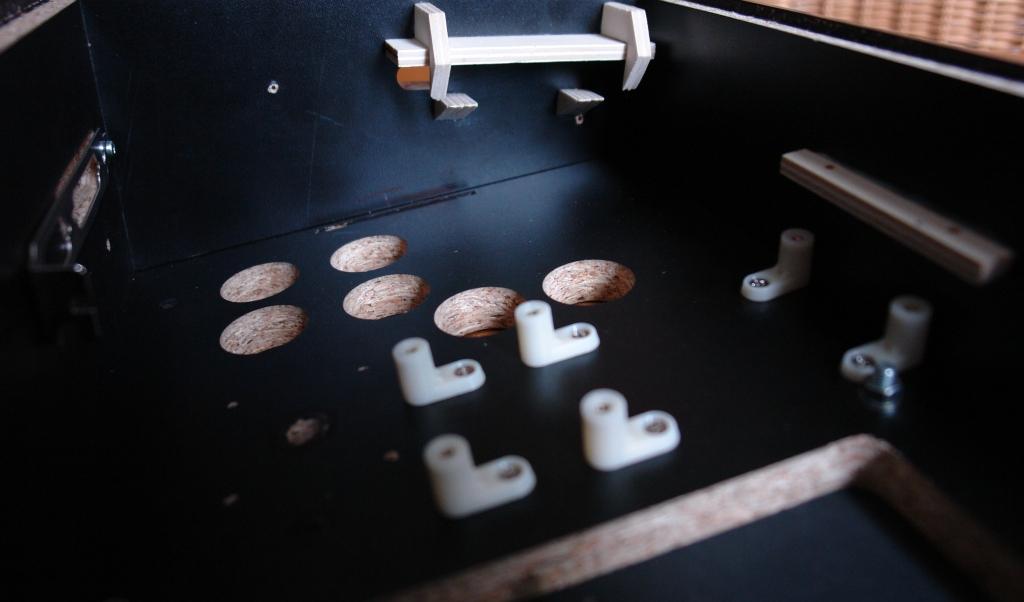
Before the controls could be mounted into the panels, some preparations had to be carried
out first. I started with the common pre- drilling of screw holes, which in the case of
the spinners was not as simple as it might seem (at least it wan't for me
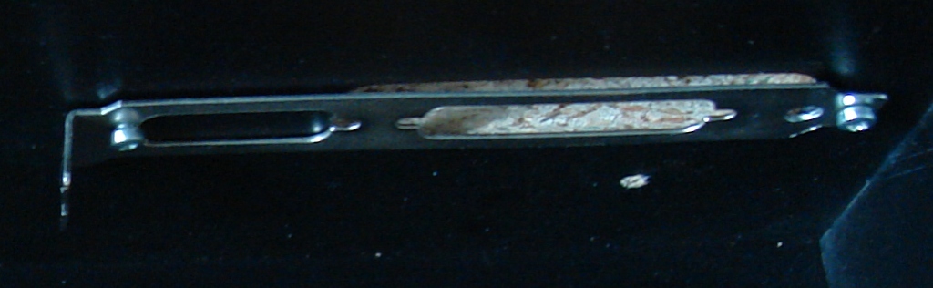
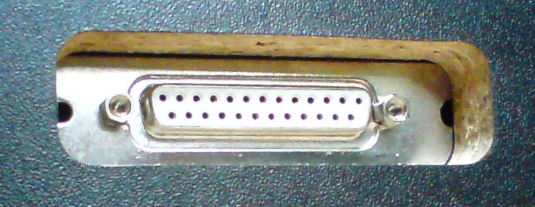
Another issue was how to fix the 25 pin SUB-D plugs which provide the connection between
the master- and the slave controller within the holes at the back side of the housings.
Fortunately, I found two suitable slot brackets in the PCs with the dead ATX power
supplies which already helped to overcome the AMOA- plug problem with the trackballs
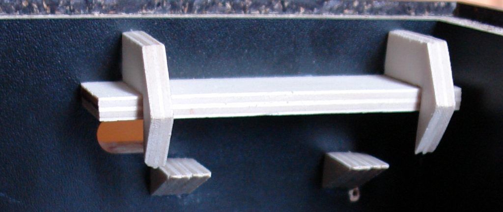
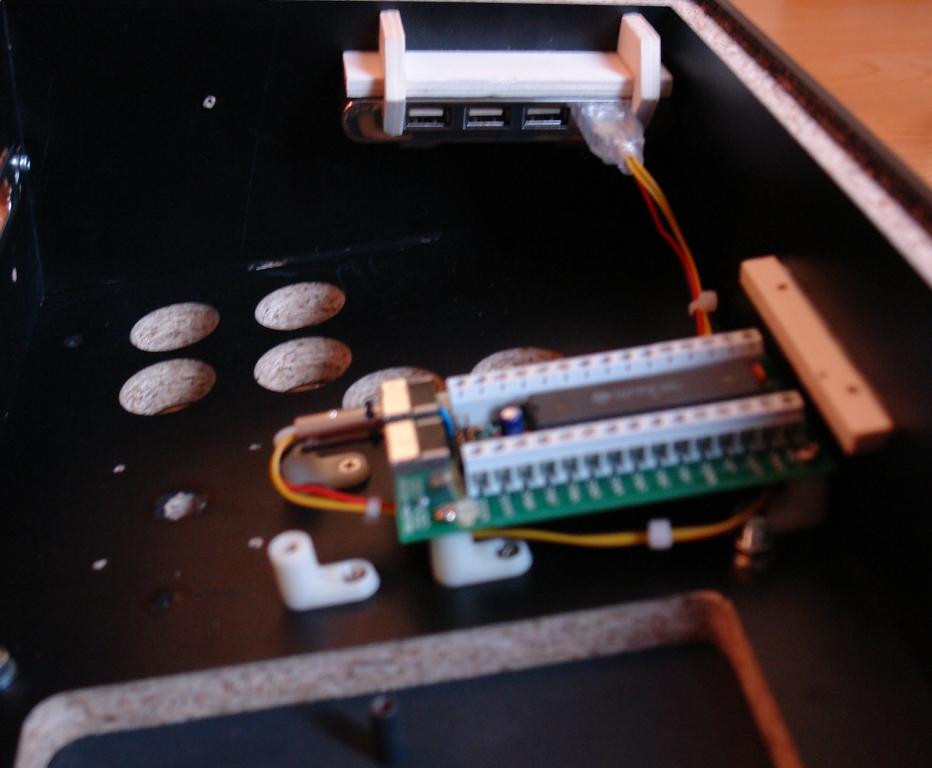
The master controller should contain the I-PAC, the Opti-PAC and the USB hub. The controller's left side already had the hole for the USB cable cut in and I needed a method to attach the USB hub there. I took some pieces of plywood and tinkered together a device like this:
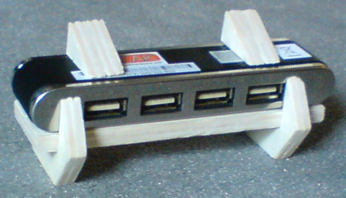
With this mounting bracket glued onto the left wall of the master controller, the USB hub slides in sideways. Once all four plugs are attached, it is fixed within the holder and can't move any longer.
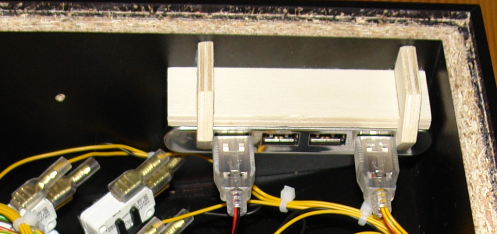
The glue sticks tight enough on the black laminate so that it was not necessary to grind
the laminate off, which would have had myself contemplate on my woodworking skills again
For the space in the controller's housing is very limited, the I-PAC and the Opti-PAC had to be installed in piggy- back configuration:
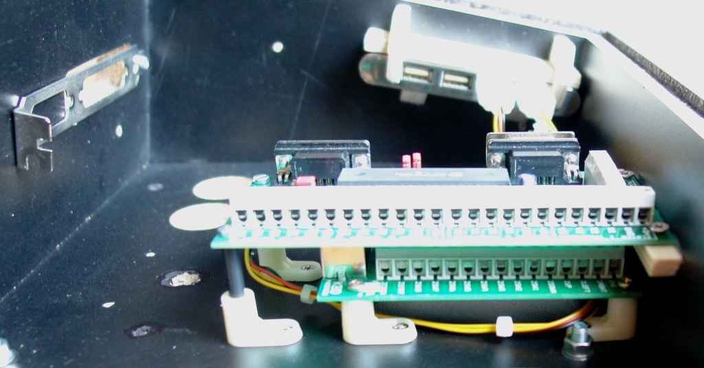
Whereas the I-PAC is attached on ordinary mounting feet, the Opti-Pac is set on risers and screwed tight in an additional small wooden bar. The risers are pieces of 3mm brass tube which are insulated with heat shrink tube. You can watch the slim trace of the self- made USB cables in the pictures above. Here, the master controller is equipped with mounting feet and bar:
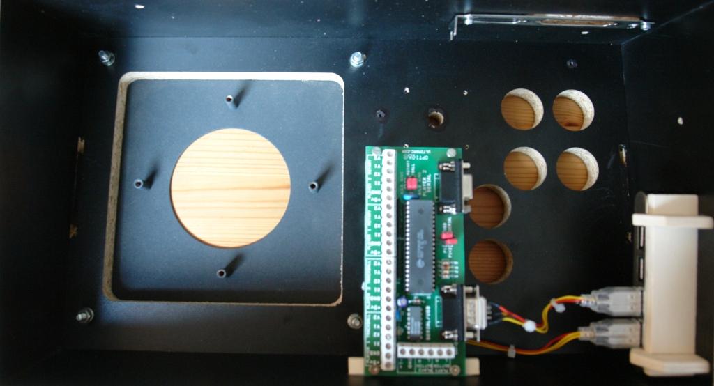
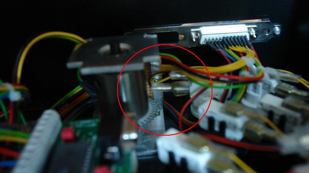
Because the I-PAC isn't accessible any longer once the Opti-PAC is in place, I-PAC and push- buttons had to be mounted first. The next two pictures show the I-PAC in its final position:
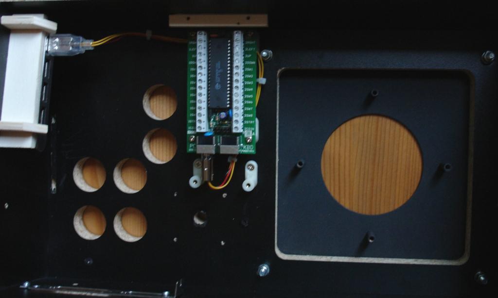
Both pictures reveal how close even the shortened PS/2 plug approaches the spinner region (those four pre- drilled small screw holes around the bigger shaft hole in the center). The buttons were mounted next. Below, you can see the micro switches with harness applied. This assembly was readily availabe from the tests in the cardboard mock- ups:
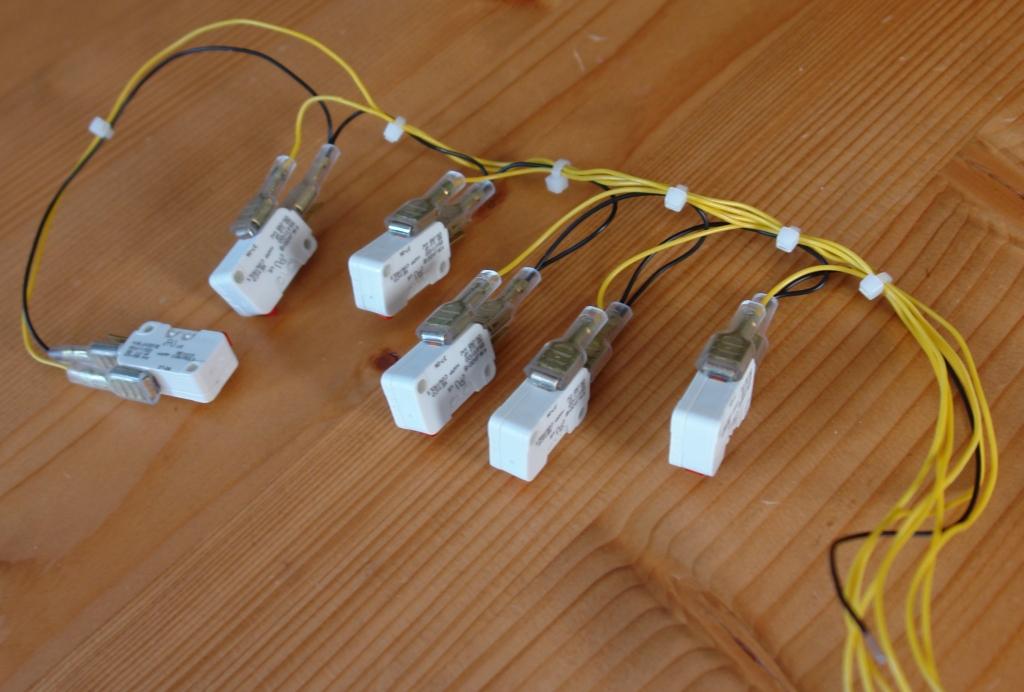
Watch the black wire (the ground) with which the switches are daisy- chained, a
technique that avoids jamming six ground wires into a single screw- down port

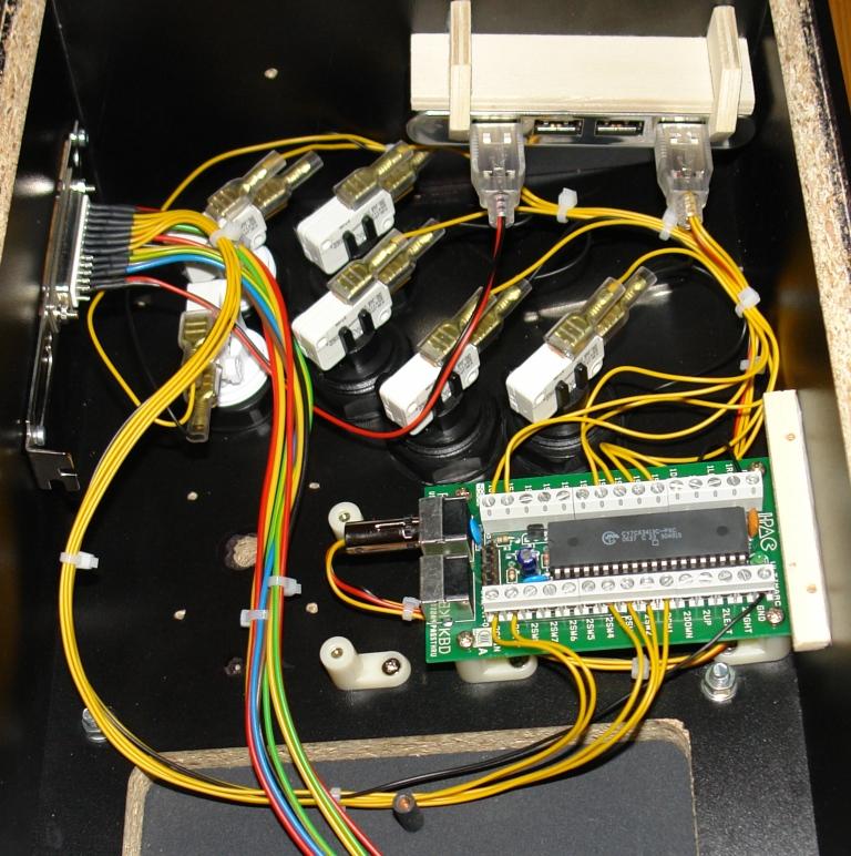
The harness of the push- buttons of player one terminates at the player- one side of the I-PAC. The wires on the player- two side are connected to the 25 pin SUB-D plug at the back side of the housing. Buttons and optical controls of the slave unit are supposed to be driven through this plug, and the connections for it's spinner and its trackball are waiting to be attached to the Opti-PAC. Finally, the red and black coloured wire pair for the slave controller's trackball illumination is already plugged into the USB hub.
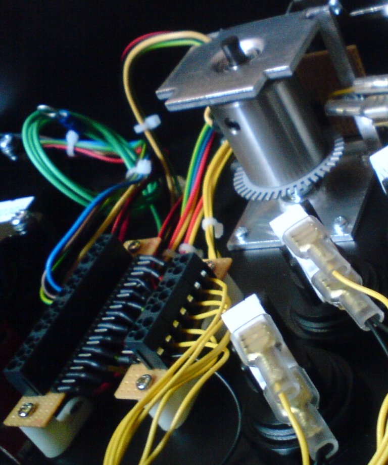
The spinner, the trackball and the Opti-PAC were installed next. This upper layer of wires includes the spinner- and the trackball cabling along with the cabling of spinner and trackball for the second player:
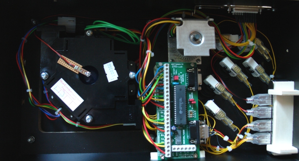
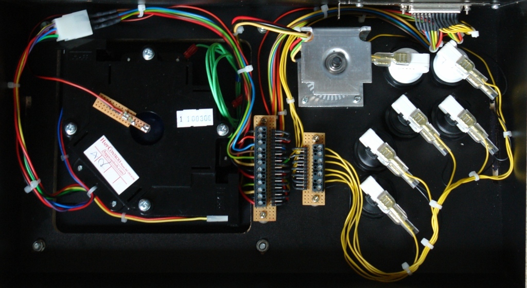
Everything fitted well into the housing of the controller, but sometimes you just have to be lucky:
Watch that microswitch sticking into the spinner's area. It can't be turned away from this position, because it belongs to the player- one start button, which has the player icon on top.
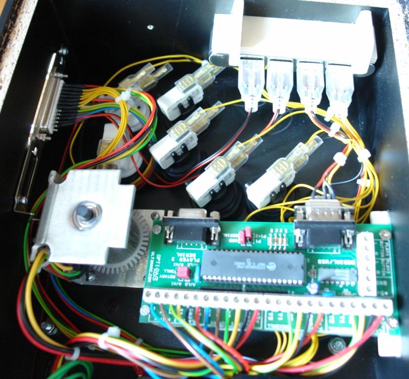
The assembly of the slave unit is much more straightforward because it doesn't contain any logic components. The controls are attachted to a set of screw terminals instead:
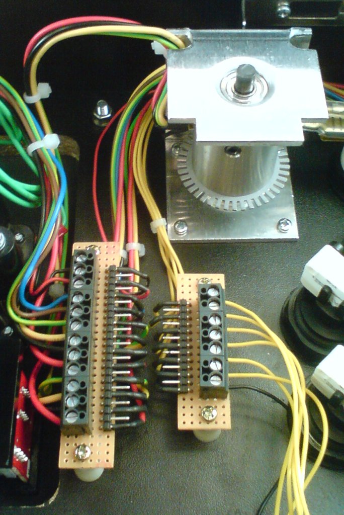
The screw terminals are connected to pin strips, on which I soldered the wires which lead to the 25 pin SUB-D plug at the controller's back side. The complete arrangement is visible here:
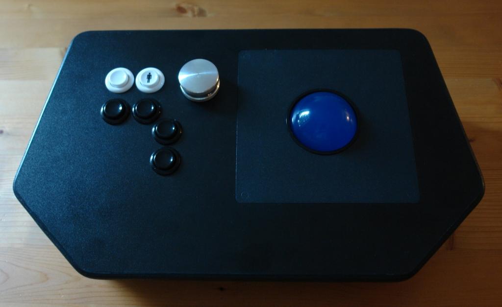
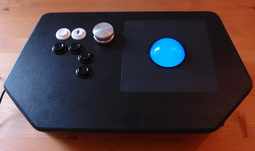
Finally, the finished master controller with and without lit trackball is shown in the pictures below. The last picure features the master controller with the slave unit attached via the 25 pin serial cable:
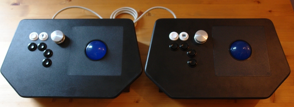
Another view of the linked controllers with lit trackballs can be found in the Start section.