This page deals with how I customized the buttons, spinners and trackballs. These
controls are designed to be attached to boards like the I-PAC or the Opti-PAC, so there
isn't really much to do unless you need special features or make wrong decisions in the
first place. Both applies to my case
Push- buttons are not highly customizable, but there was a problem with the start buttons which have the player icon on top. This allows only for one orientation of the microswitch underneath, which sticked out the wrong way and collided with the nearby coin- insert button. However, it was very simple to unmount the inner part of the button, turn it around 180 degrees and reattach it. You can see diagrams and even watch movies at Happ's website, which describe the disassembly- and reassembly process of their push- buttons in detail.
SlikStik's Tornado spinner comes in two variants which differ from each other in the logic board mounted on the spinner's backside:
| • | The Opti-PAC TTL version uses two opto switches which read a quadrature signal from the encoder wheel. This signal is routed through four wires going directly to the Opti-PAC's screw terminals. |
| • | The USB/PS2 version has the same generator for the quadrature signal, but some additional logic chip translates this into horizontal and vertical mouse movements. These boards are plugged straight into a PC's USB or a PS/2 port, and the operating system recognizes them as mice. |
I purchased my Tornado spinners as USB/PS2 devices, because they were my first optical controls. This was perfectly fine until I got the idea of building special control panels where the spinners are used in combination with trackballs. The latter require an Opti-PAC anyway, for which the TTL version of the spinners would have been the better choice.
After a little contemplation and googling, I stumbled upon the D.I.Y. Optical Sensor section of Ultimarc's website which describes the construction of a simple quadrature signaller made of three electronic components (two opto switches and a resistor). Here is what I did in order to replace the original logic board from SlikStik:
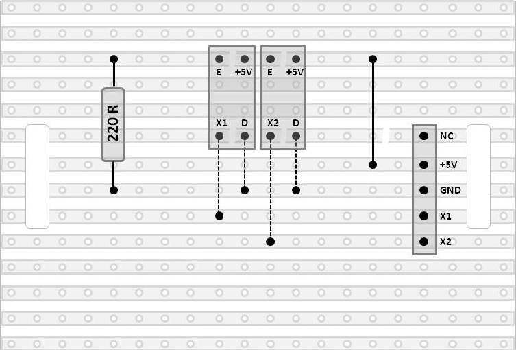
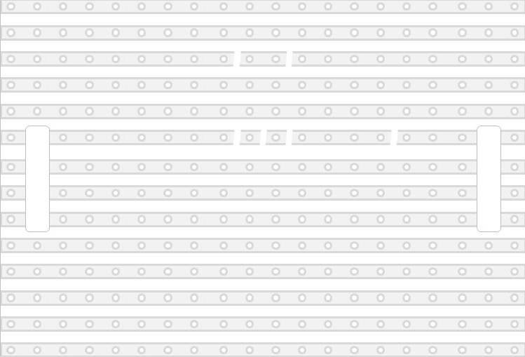
| I cut a piece of veroboard into the size of the SlikStik board and drilled in the longish mounting holes. The stripes proceed horizontally, i.e. parallel to the encoder wheel. The following pictures show my interpretation of Ultimarc's idea with and without parts fitted in (click for enlarged view). With these schematics, the fabrication of working replacement boards for the Tornado spinner is as easy as counting rows and columns of solder spots. |
| The pictures above show the component side of the board with the solder strips shining through from underneath. It is necessary to intersect some of these strips at positions which are clearly visible in the view of the empty board on the right side (six gaps altogether). The four dotted lines represent micro-cables and the solid line depicts a wire strap. In case you have a 4 pin connector available for the connection to the Opti-PAC (I couldn't find one), the NC- pin together with the security gap on its left side drop out. Finally, the acronyms stand for |
| E: | Negative pin of the infrared LED (Emitter of the opto switch) | |
| D: | Negative pin of the phototransistor (Detector of the opto switch) | |
| X1: | Signal pin of opto switch 1 | |
| X2: | Signal pin of opto switch 2 | |
| GND: | Ground | |
| NC: | Not connected |
|
Ultimarc's D.I.Y. Optical Sensor page refers to the QVB11323 opto switch from
Fairchild. I replaced this with the TCST 2103 from Vishai Telefunken, which is more
easily available here and seems to be an adequate replacement part. As recommended, I
added a 220R resistor acting as a common pre- resistor for the two infrared LEDs of
the opto switches, which are connected in series. The board's layout has to take into
account that no part should collide with the spinner's flywheel. Where I was not able
to incorporate proper routing of signals by design, I corrected this with green micro
cables on the component side of the veroboard. These micro cables are clearly visible
in the pictures below |


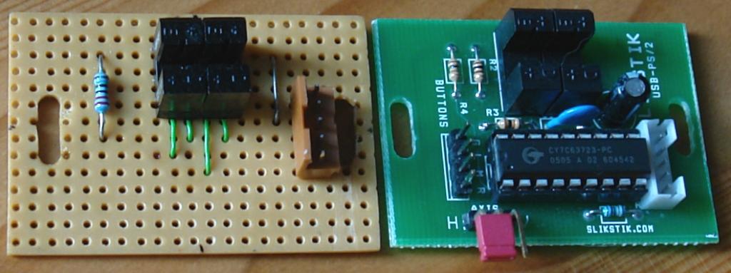
The redesigned Tornado spinners work very nicely with the Opti-PAC. They show the same pointer speed in Windows and the same sensitivity in MAME as when operated with the SlikStik boards. This is not really surprising, because these boards use very similar opto switches, which are placed at the same positions as they are located in my replacement boards. I still wonder whether the quadrature signal couldn't be tapped off the original boards as well. Here you can see both boards in comparison:
Happ's wiring logic of the trackballs is very straightforward. The signals of two quadrature signallers, one for horizontal and one for vertical movement, are routed through six wires (the grounding and the +5V VCC are shared). The wires should be attached to six screw terminals of the Opti-PAC - not quite, unfortunately. Happ's wiring harness terminates in a six pin AMOA (Amusement and Music Operators Association) compliant plug. The standard treatment is to chop this plug off and screw down the now free wires in the Opti-PAC's terminals.
Somehow I disliked this idea. I was more pleased with the imagination that the trackball on occasion could be detached from my control panel and moved into a Golden Tee Golf cabinet or the like. As far as I understand, the 3" trackballs are designed for those games, in which they are operated with use of AMOA plugs. Of cause, there is no Golden Tee Golf in my neighbourhood and swapping my trackballs into such a game will never happen, but nevertheless I like this vision...
The question was, what to do now. The female counterpart for this plug was impossible to find at the usual electronics shops. Eventually I realized that the pins of the AMOA plug are the same as in those molex plugs, which are used in common PC hardware like hard disks. So I took a dead ATX power supply, cut the wires off the housing and released the numerous single female pins from their molex receptacles. The red, black and yellow cables were ready to use. I soldered cables with the missing green, blue and purple colour on some spare connector pins and insulated the metal surface and solder joints of all pins thoroughly with heat shrink tube. You can see the result here:

When ordering the trackballs, I couldn't resist the traslucent blue colour option for which the trackballs have to be illuminated. There is a mounting hole at the bottom of each trackball where a wedge base lamp holder can be screwed in. I couldn't find the illumination parts in the diagrams at Happ's website, but interestingly they appear in SUZO's catalog (Happ's distribution partner). This might be a hint that this lamp is already deprecated.

However, Happ's lamp has to be powered by 14 volts which is quite impracticable having an USB hub available for power supply. So I decided to use a high power LED instead, for which the +5V of an USB connector are more than sufficient. By the way, this is the purpose of the USB plug protruding under the trackball, which you might have noticed on the image of the controls in the design - section. I found cheap LEDs, which deliver 18000MCD and run on U_led=3.2V at I_led=20mA. With a source voltage of U=5V, a pre- resistor is necessary to limit the current which runs through the LED. The value of this resistor calculates to
LED and pre- resistor were soldered on a small piece of veroboard, which was applied at
the bottom of the trackball with nylon thread. The mounting hole for the illumination came
in very handy and nearly served the purpose, it was designed for

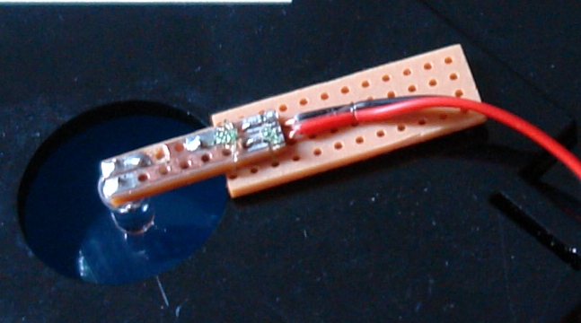
As you can see, the LED is placed very close below the traslucent blue sphere, providing for maximum light effect.